EMS P-Tester (EMS Permeation Tester)
EMS P-Tester short description
With the EMS P-Tester, permeation measurements are carried out according to the dynamic measuring principle developed by EMS. With the permeation test, the permeability of fuel system components is determined by recording the hydrocarbon permeability under defined measurement conditions. The dynamic measurement principle is characterised by two circuits, the fuel circuit and the carrier gas circuit.
The sample, a part or an assembly of parts through which in normal use fuel flows, for example a fuel tube, is fitted into the measurement chamber, the receptacle, and test fuel is circulated through it at a defined volumetric flow, defined temperature and defined pressure. The receptacle is heated to the desired temperature to simulate conditions of normal use, for example, a motor. External to the sample flows a defined carrier gas volume (N2) which transports permeate to the activated charcoal filters, where it is adsorbed. The speed of the mass increase of the filter medium, in proportion to the inner surface area of the sample is defined as the rate of permeation or the permeability of the sample and is indicated in conjunction with the measurement conditions.
The dynamic principle distinguishes itself from a static process through two essential advantages:
- The fuel composition can be held more or less constant during measurement.
- The ambient temperature and fuel temperature are independently adjustable.
To evaluate an experiment, the mass increase of the activated charcoal filters due to hydrocarbon absorption over time is displayed in a diagram. The permeation rate is calculated from the slope of the line constructed using linear regression and set in proportion to the inner surface area, or for tubes also in proportion to their length.
The change in length due to swelling is determined by means of a special measurement process.
The basic construction of the EMS P-TESTER is characterized by two receptacles and one fuel circuit, in which the samples in both receptacles are aligned in series with flow being generated by a controllable gear pump, and by a carrier gas circuit for each receptacle. At the same time there are two identical tubes (same plastic,same dimensions, same production) inside both receptacle. With this layout you can realize, evaluate or correct possible deviations quickly.
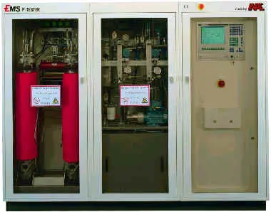
EMS P-Tester A02
The EMS-P-Tester is used to determination of the permeability of fuel system components by registration of the permeability of hydrocarbons under defined measurement conditions according to a dynamic measurement principle.
- full automatic
- balance resolution 0.01 g
- weight intervals adjustable
- controlled ventilation
- controlled overpressured electric cabinet
- CH-Gas controller
- Alarm signals for external use
- wired safety functions
- programmed safety actions
- non smoking
- ventilated room
- anti-static, fuel resistant flooring
- vibration free
- no other devices with explosive atmospheres
- fresh air, exhaust
- cooling water in- and outlet
- N2 inlet
- connection for FID
- 3 x 380-400/220-230V, 50/60Hz, 7kVA
- transformator for other line voltages(option)
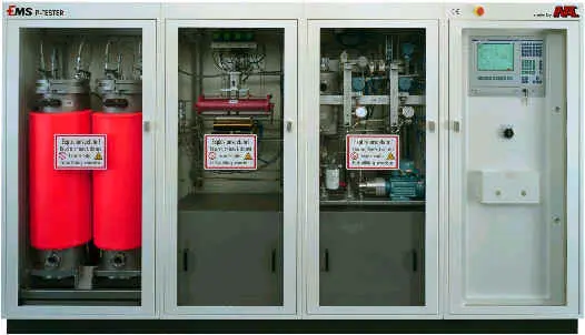
EMS P-Tester A03
The EMS-P-Tester is used to determination of the permeability of fuel system components by registration of the permeability of hydrocarbons under defined measurement conditions according to a dynamic measurement principle.
- full automatic
- balance resolution 0.01 g
- weight intervals adjustable
- controlled ventilation
- controlled overpressured electric cabinet
- CH-Gas controller
- Alarm signals for external use
- wired safety functions
- programmed safety actions
- non smoking
- ventilated room
- anti-static, fuel resistant flooring
- vibration free
- no other devices with explosive atmospheres
- fresh air, exhaust
- cooling water in- and outlet
- N2 inlet
- connection for FID
- 3 x 380-400/220-230V, 50/60Hz, 7kVA
- transformator for other line voltages (option)